End Fed Random Wire Antenna
Background
The March 1936 issue of QST magazine by the American Radio Relay League (ARRL) contains an article titled "An Unorthodox Antenna" by Yardley Beers (W3AWH) where he describes an antenna designed by his friend Mr. H. J. Siegel, W3EDP. This antenna is commonly known as the W3EDP antenna. It is a random wire antenna similar to the Zepp Antenna developed by Hans Beggerow in 1909. The W3EDP antenna was developed by trial and error. It was an all band antenna at the time, covering 160m, 80m, 40m, 20m, and 10m. The best results obtained during the testing were an 84' radiator and a 17' counterpoise on all bands except 20m where a 6.5' counterpoise performed best.
Despite the name, it's important to note that random wire antenna lengths are not random. Random wires present a high impedance on any frequency that is a half wave length (or a multiple of a half wave length) of any desired frequency. Jack (VE3EED) has crunched the numbers and 84' is one of the thirteen "good" lengths. Additionally, Mike (AB3AP) has developed software to experiment with different band combinations and lengths; he has confirmed that 84' with a 17' counterpoise is a good choice for 80m and up. The W3EDP and Mike disagree on the suitability of this antenna for 160m. This is because random wire antennas should be at least one quarter wave length long on the lowest desired operating frequency in order to perform really well, and the length 84' is less than a quarter wave length on 160m.
In the original antenna design, the antenna was coupled with the final power amplifier by a tuned tank circuit. Placing the feed point at the antenna tuner is fine for QRP output levels (5W or less) where RF expose will be low. Remember that the radiating element is going to be close to the tuner in this scenario; if you're using higher power levels, the antenna can be fed with a coax feedline and an unun (typically a 9:1). Variations include using 17' of twin lead ladder line with one side open and the other connected to 67' of wire which gives a 17' counterpoise and 84' radiator. If coax is being used to feed the antenna, a line isolator (1:1 unun) should be used to choke common mode currents. If the antenna has a dedicated counterpoise, then the line isolator should be attached at the antenna feed point. If the intent is to use the coax shield as a counterpoise, then the coax should be at least 30' long and the line isolator should be placed at the output of the antenna tuner.
Overview
Due to limited space, this build will feature a 29' radiator and a 17' counterpoise. This configuration covers 40m through 6m, and it's a bit of a compromise on 40m. Use the links in the "Reference" section below to find alternative lengths.
Bill of Materials
Quality and upgradability are the key drivers for part selection. Operating on 160m with 100W isn't an option due to size constraints and love for QRP, but having the option to replace the radiator if more antenna space becomes available or increase the power if desired is atrractive. The following antenna system should cover 160m through 6m at 100W CW/SSB and 30W DIGI provided a long enough radiator is used (see disclaimer below).
- DX Engineering High Visibility Antenna Wire DXE-VIZ14-G250
- 3M Products Scotch Multi-Colored Premium Vinyl Electrical Tape 35-3/4X66FT-OR
- DX Engineering Coaxial RF Connector Adapters DXE-538-2
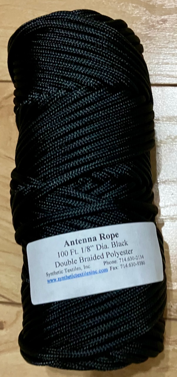
- Synthetic Textile Industries Antenna Support Rope DBR-125-100
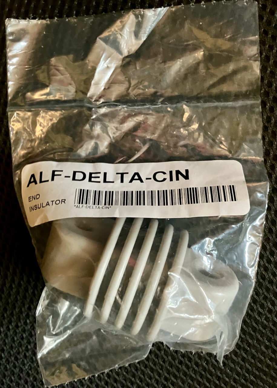
- Alpha Delta End Insulators DELTA-CIN (2)
- mAT-TUNER Automatic Antenna Tuners MAT-30
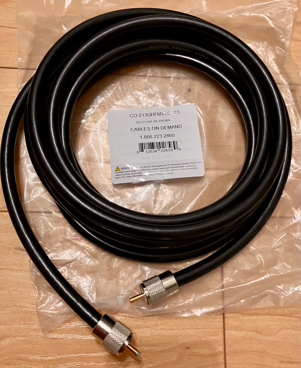
- Amphenol CO-213UHFMX20-015 Black RG213 UHF PL-259 Coaxial Cable, 50 Ohm, Male to Male, 15'
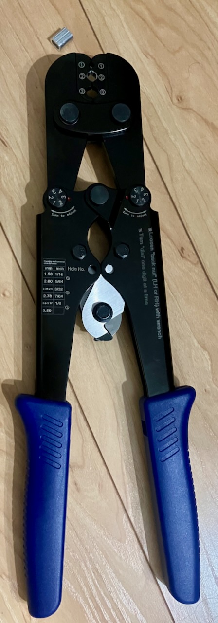
- CAMWAY Wire Rope Crimper Crimping Tool Wire Rope Cutter from 1/16inch to 1/8inch +100pcs 1/8inch Aluminum Crimping Loop Sleeve + 50pcs M3 Stainless Steel Wire Rope Cable Thimble Rigging
- M0CVO Antennas 1:1 Line Isolator
- The M0CVO Antennas 9:1 High Power UNUN (400W)
The Build
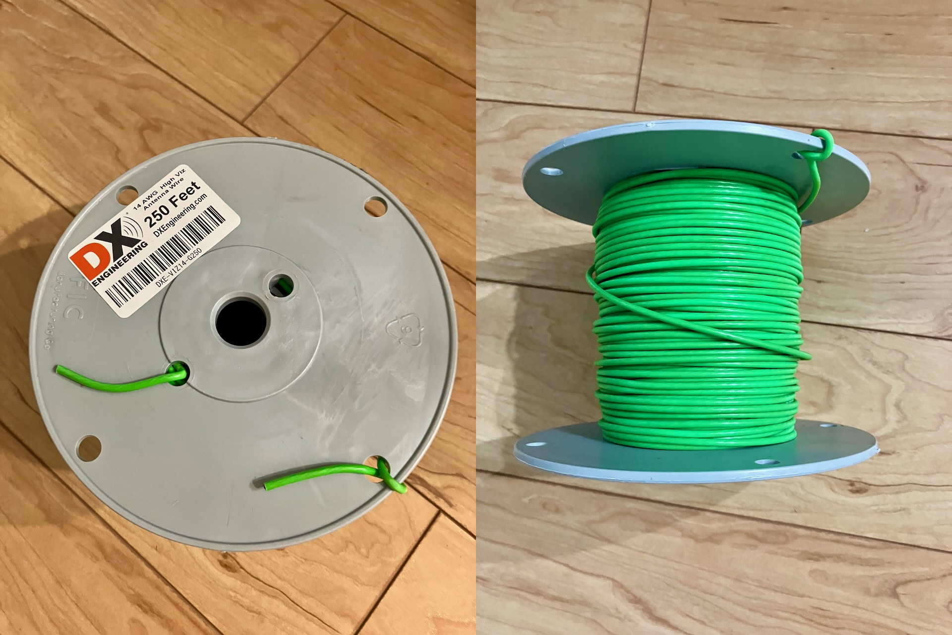
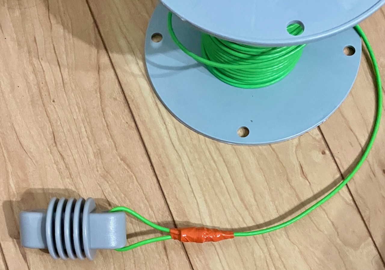
The first step is to untie the wire from the spool. Then cut off about a foot of wire to remove any damage that may have occurred when tying off the end.
Locate the end insulator.
Locate the crimper tool.
Thread the wire through the loop sleeve and end insulator and then back through the loop sleeve. Finally, crimp it.
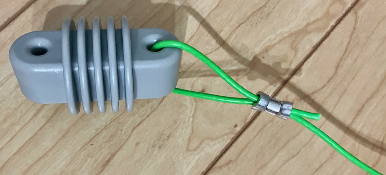
Since the loop sleeve is metal and deformed by the crimper, there is a good chance that bare wire is touching the loop sleeve. I wrap the loop sleeve in electrical tape to insulate it.
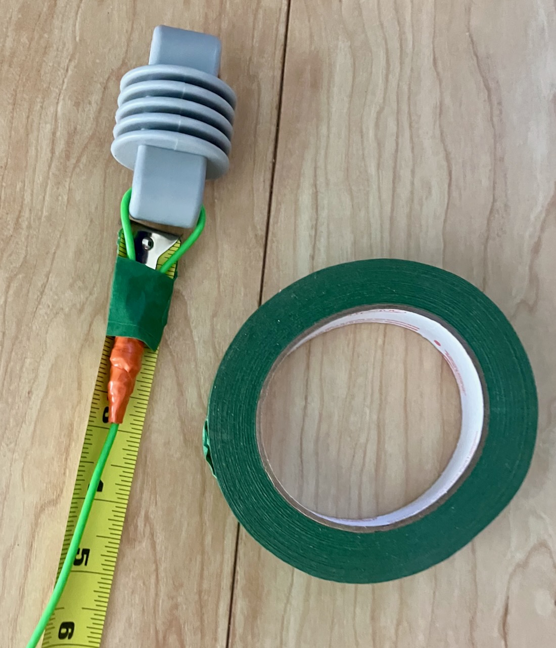
Next measure out a length of wire for the counterpoise. One simple way to do this is to use painter's tape to secure the wire to a measuring tape.
At the other end of the wire, strip a quarter of an inch of insulation. Put a ring terminal on it. Crimp the terminal. Then solder it to ensure there is a solid connection.
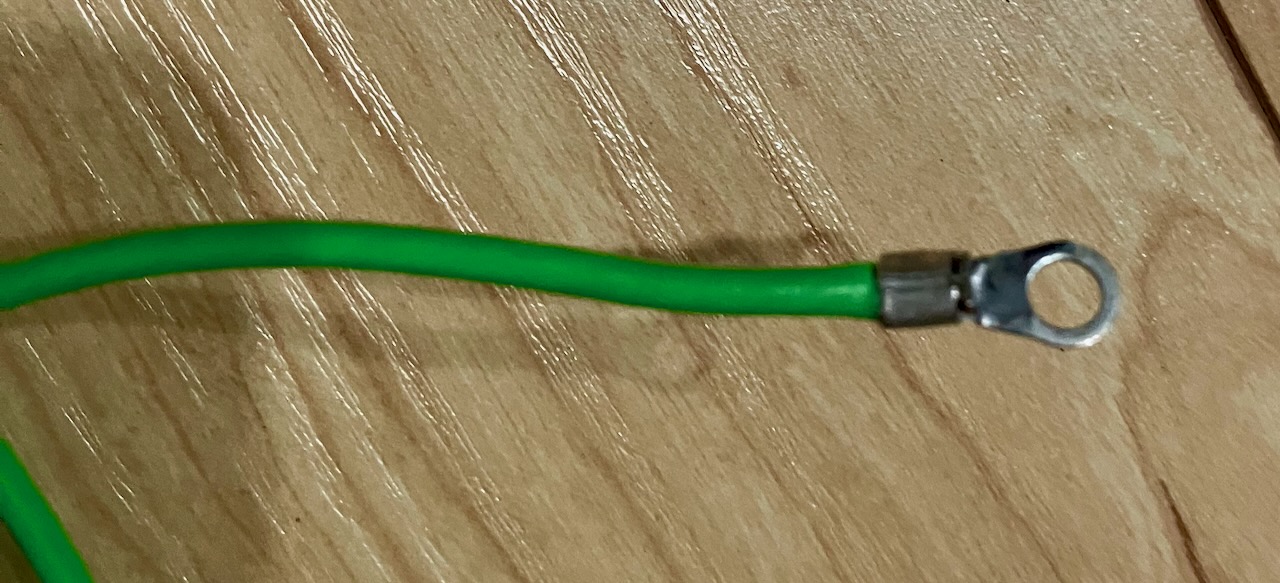
Repeat the above for the radiating element.
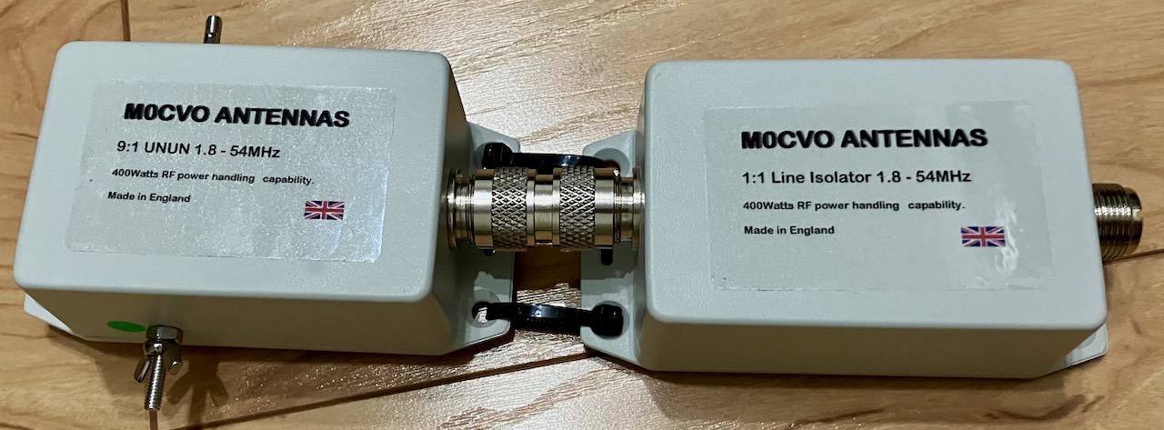
Next, use a PL-259-to-PL-259 adaptor to connect the 9:1 unun to the 1:1 unun. Zip ties can be employed to ensure the ununs don't turn and unscrew the connection.
Connect the radiator and the counterpoise as well as some high quality coax such as RG-213.
Configure the antenna with the radiator in an invetered V orientation over a horizontal counterpoise. Anchor the ends with high quality antenna rope.
Initial Results
With an appropriate tuner, the antenna tunes up on all bands from 6m through 40m. The results are looking promising. In the first evening of use, several QSOs were made on 40m with SSB at 10W. Additionally, a CW QSO to Nebraska was made with 5W on 20m.
References
- The "Best" Random Wire Antenna Lengths
- Random Wire Antenna Lengths
- ARRL Random Wires Page
- Field Report: Let’s build a super simple antenna on-site and activate this park!
- QST Magazine (October 1936)
Disclaimer
Disclaimer: I am not an engineer. I just enjoy messing around with electronics on the weekends and sharing my experiences. Electricity and associated tools such as soldering irons can be dangerous and possibly result in death, injury, and/or property damage. Don't try this at home.