Transforming a Computer Mouse into a CW Key
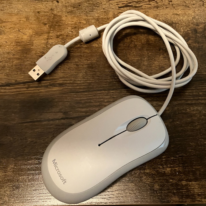
So I decided to modify a computer mouse to be a CW key. I'm probably not the first person to think of this, but I've never seen it done before. I had an old mouse laying around that didn't work anymore. The most likely root cause was a broken cable. The mouse is a Microsoft Basic Optical Mouse. They sell new for between $10 and $20 Canadian, so even if you buy one to mod, it is still very inexpensive for a CW key.
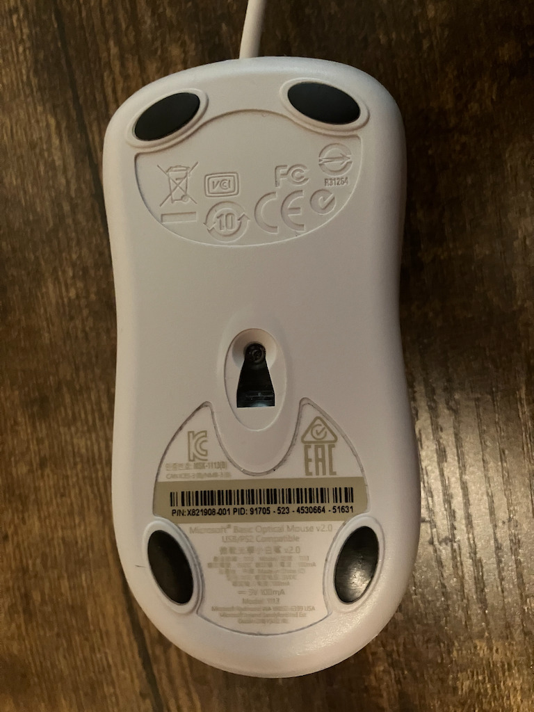
The first step is to open up the mouse so that we can operate on it. To do this, you'll need a small phillips head screwdriver. The first step is to peel away the serial number sticker to expose the screw.
I used a tiny flathead screw driver to remove the sticker. Then, I unscrewed the screw. The front part of the top of the mouse is slotted into two clips which are on either side of the cable. Slide the top of the shell back a few millimetres to unslot it. Then you can pull up to completely remove the top. The PCB just sits in the case without any screws, so it can easily be lifted out.
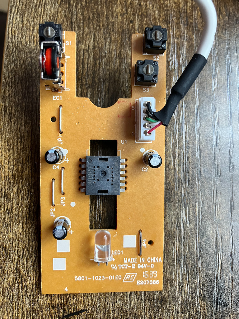
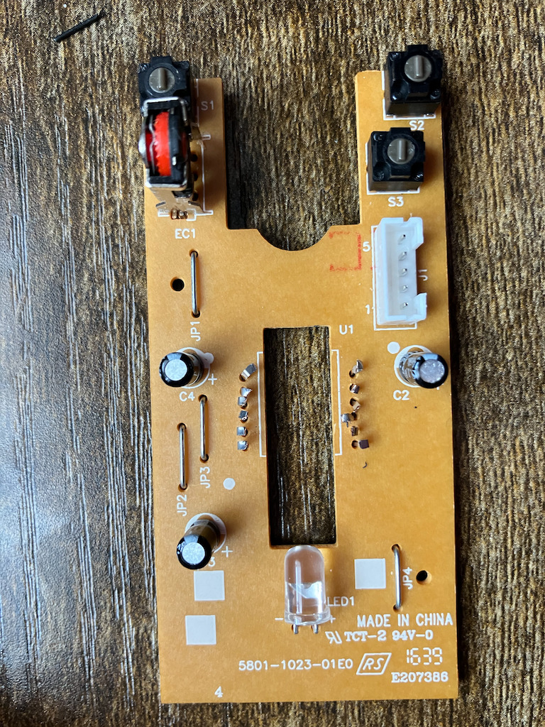
It's a simple, inexpensive single layer board. There isn't much on the board, three buttons for left click, right click, and middle click on the scroll wheel. There are a few capacitors and an encoder for the scroll wheel. The chip in the center is the brains of the operation and includes the optical sensor.
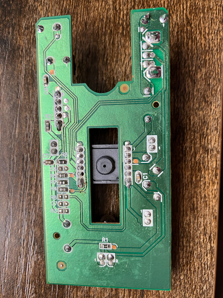
The underside has a handful of resistors and capacitors. So now it is decision time. How do we interface with the buttons and connect to the outside. There are a few options here.
Option one is to use the existing header and mouse cable. Thin (e.g. 28 AWG) wire can connect the button terminals to the header. Pin 4 of the the header is already connected to ground. I chose not to take this approach. There is very little clearance under the board inside the case. The solder on the board is old and difficult to get flowing without damaging the board. Additionally, I wouldn't be able to use the cable the mouse previously had as I'm pretty sure it had a break in it.
Option two is to cut out the IC and wire into the push button pins. This is the approach I took. Using the continuity function on my multi-meter, I found that the buttons were pins 1, 9, and 12. Ground was pin 4.
I removed the IC with side cutters leaving as much of the pins as possible so that I'd have something to solder onto.
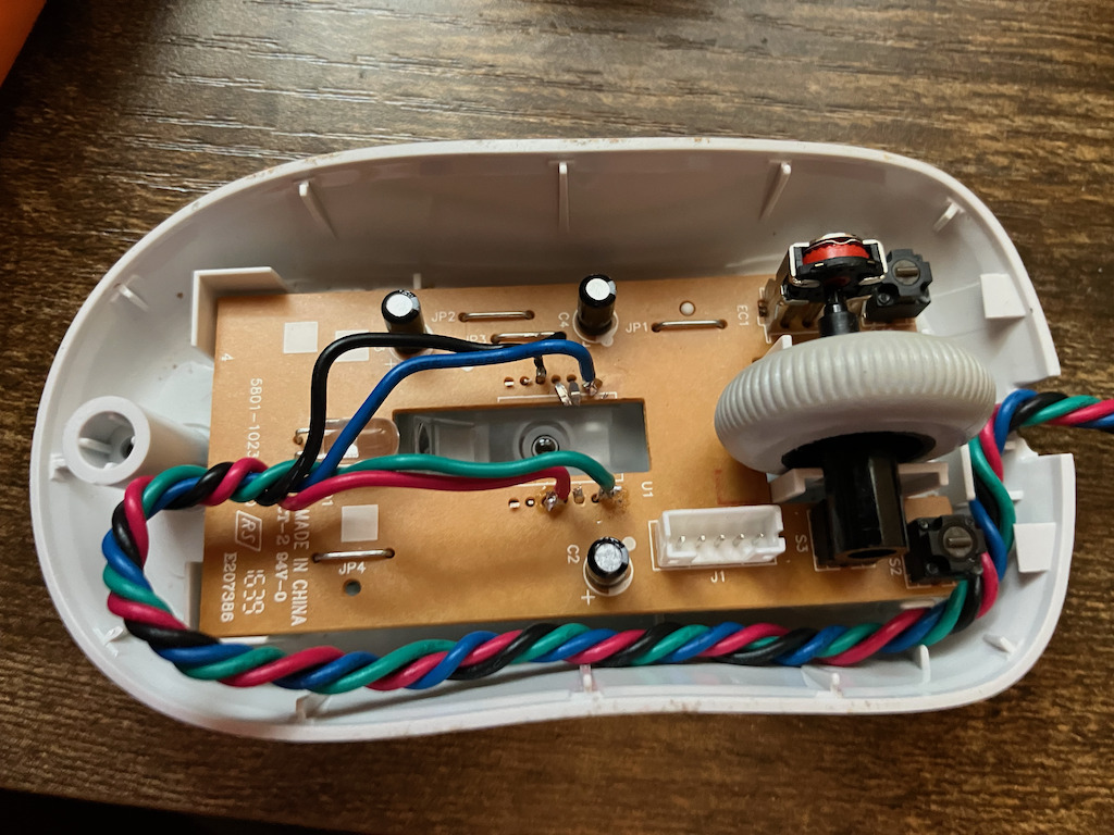
I tinned the pins and the wires and then I soldered them together. I pushed some of the other pins down or cut them so that they wouldn't be in the way. I used what wire I had, just some plain old hook up wire. I twisted it together to form a cord. The cord needs to route near the header as there is a trough for the cord to pass around the top of the board and out the opening. This route provides some strain relief as well. The final step is putting the case back together.
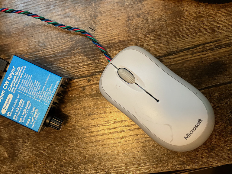
The finished product looks like a normal mouse with a slightly different looking cord. I used a 3.5mm Terminal Block Cable to connect the wires to a 3.5mm plug. This allows me to change the wiring with a screwdriver (e.g. to make it a cootie key or reverse the buttons).
In conclusion, it was a fun weekend project. I hope you enjoyed learning about it. I have a youtube video demo: Demo: Microsoft Mouse converted into a CW Key.
Disclaimer: I am not an engineer. I just enjoy messing around with electronics on the weekends and sharing my experiences. Electricity and associated tools such as soldering irons can be dangerous and possibly result in death, injury, and/or property damage. Don't try this at home.